Tevo Tarantula Wiring Overview
The Tevo Tarantula is a popular and affordable 3D printer known for its ease of assembly and modification. However, the wiring process can seem daunting to beginners. This guide simplifies the Tevo Tarantula wiring process, providing step-by-step instructions and helpful tips to ensure a smooth and successful build. Understanding the wiring is crucial not only for initial setup but also for future troubleshooting and upgrades. This guide will help you navigate the various components and connections, enabling you to bring your 3D printing projects to life. Follow these instructions carefully, and you’ll be printing in no time. Remember to take your time and double-check all connections before powering on your printer. Let’s get started on making the wiring process easy.
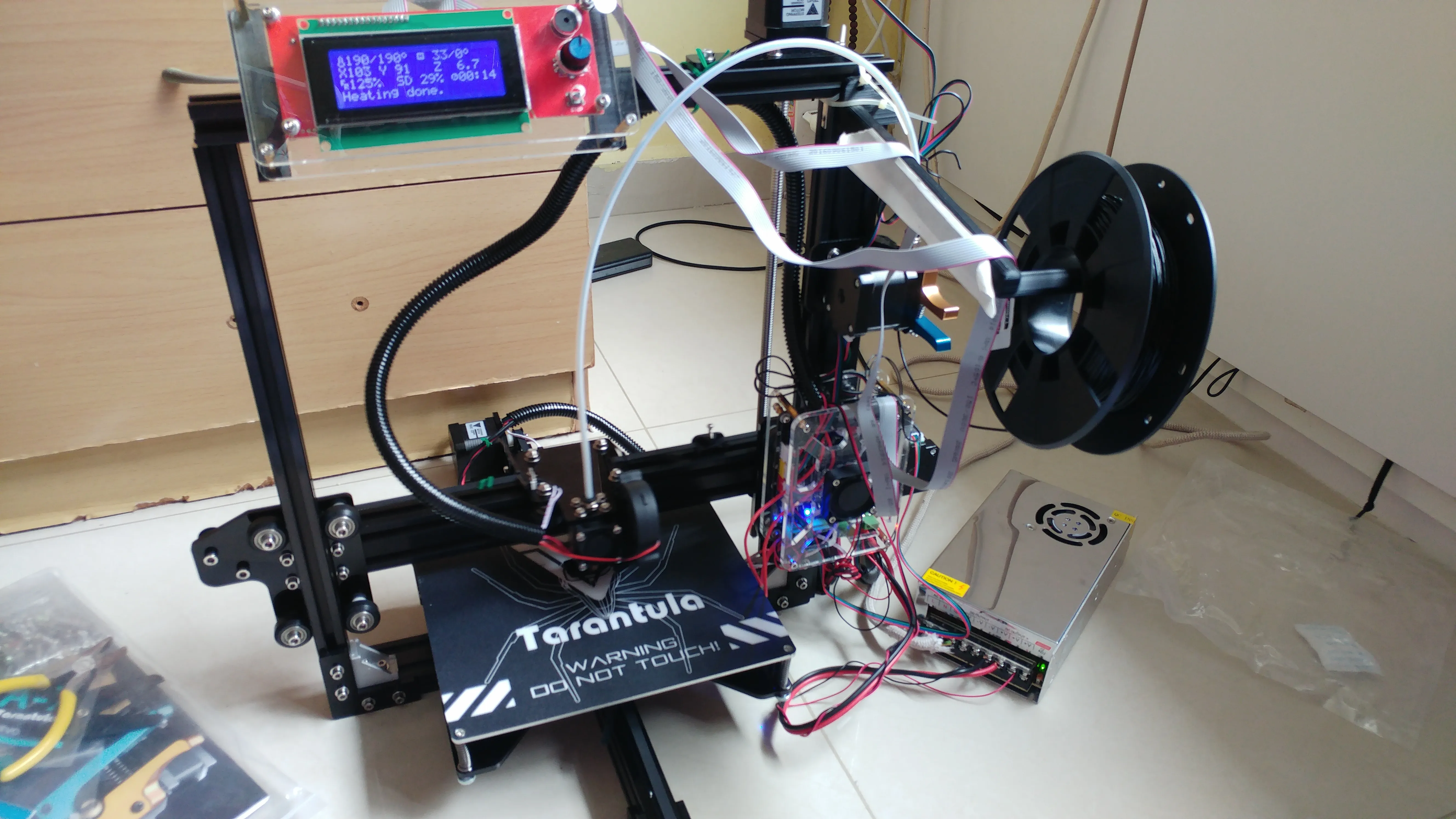
Components of the Tevo Tarantula
Before diving into the wiring, familiarize yourself with the Tevo Tarantula’s core components. This includes the power supply, mainboard, stepper motors, endstops, heated bed, and hotend. The power supply provides electricity to the entire system, while the mainboard acts as the brain, controlling all the functions. Stepper motors drive the movement of the X, Y, and Z axes, as well as the extruder. Endstops are sensors that determine the printer’s limits of movement. The heated bed provides a surface for the first layer of your print to adhere to, and the hotend melts and extrudes the filament. Knowing where each component is located and its function will make the wiring process significantly easier. Proper understanding of these components is the base of any 3D printer.
Power Supply Wiring

Wiring the power supply correctly is vital for safety and functionality. The Tevo Tarantula typically uses a 12V or 24V power supply. Locate the input terminals on the power supply for the mains AC input (typically labeled L, N, and GND). Connect the AC power cord wires to these terminals, ensuring that the connections are secure and properly insulated. On the output side, locate the terminals labeled +V and -V. These are the DC output terminals that supply power to the mainboard and heated bed. Pay close attention to polarity; +V connects to the positive terminals, and -V connects to the negative terminals. Use appropriate gauge wires for the current draw. Always double-check all connections before applying power, and consider using a multimeter to verify the voltage output.
Connecting the Mainboard
The mainboard is the central hub of the 3D printer, so proper wiring is critical. Begin by connecting the power supply output wires (+V and -V) to the appropriate terminals on the mainboard (usually labeled as such). Next, connect the stepper motor cables to their designated slots. These are typically labeled X, Y, Z, and E (extruder). Make sure to insert the connectors in the correct orientation. The mainboard also needs connections to the heated bed and the hotend. These will usually be screw terminals. Refer to your mainboard’s manual for specific terminal locations and wiring diagrams, as they can vary. Ensure the connections are snug to avoid any electrical shorts or malfunctions during operation.
Wiring the Stepper Motors
Stepper motors control the movement of the printer’s axes and the extruder. Each stepper motor has a cable with four wires. These cables connect to the mainboard’s stepper motor drivers. The connection orientation is important for the direction the motors turn. Incorrect wiring here can cause the printer to move in the wrong directions. The motor connectors are usually keyed, which helps in proper insertion. If a motor moves in the wrong direction, you can usually reverse the wiring by switching the order of two wires in the connector, but it is also possible to change the firmware. Remember, a correct motor wiring setup directly affects the accuracy and precision of your 3D prints. Always double-check all wire connections.
Wiring the Endstops

Endstops are crucial for defining the limits of the printer’s movement along each axis. They prevent the print head from crashing into the frame. The Tevo Tarantula uses mechanical endstops, which typically have two or three wires. These connect to the mainboard’s endstop connectors. The wiring configuration depends on the type of endstop and the mainboard’s design; consult your specific printer’s manual for wiring instructions. Ensure the endstops are properly mounted and aligned so they are triggered when the print head or bed reaches the end of its travel. Properly wired endstops ensure your printer’s safety and accuracy. Without endstops, the print head or bed could move beyond the printer’s frame, causing damage to the printer.
Wiring the Heated Bed
The heated bed is essential for good bed adhesion, especially when printing with materials like ABS. The heated bed typically has two wires for power, which connect to the mainboard’s heated bed output terminals. These terminals are typically rated for high current and can handle the power requirements of the heated bed. Make sure the connections are secure. It is highly recommended to use a solid-state relay (SSR) to control the power to the heated bed. An SSR provides better safety and can handle higher currents than the mainboard’s output. Incorrect wiring can damage the mainboard and the heated bed itself. Double-check the polarity of the connections, and never exceed the rated current of any of the components.
Wiring the Hotend
The hotend is where the filament is melted and extruded. It includes a heater cartridge and a thermistor for temperature sensing. The heater cartridge has two wires that connect to the mainboard. The thermistor has two wires that connect to the mainboard’s thermistor input. Make sure the heater cartridge wires are connected to the correct output and that the thermistor wires are connected to the correct input. Polarity usually does not matter for these connections. Ensure the connections are secure and that the wires are properly insulated to prevent shorts. Temperature sensors are very sensitive; be careful when handling the thermistor wires as they are fragile. A properly wired hotend ensures proper temperature control and a successful print.
Troubleshooting Common Wiring Issues

Motor Not Moving
If a motor isn’t moving, first, check the wiring. Ensure the motor cables are securely connected to the mainboard’s stepper motor drivers. Verify the polarity of the connections. Also, check the motor driver itself; it may be faulty, or the driver’s voltage may be incorrect. Firmware settings can also prevent motor movement. Check the motor driver current limit setting to make sure it is correctly set for the motors used. In some cases, the motor might be disabled in the firmware settings. If the motor makes a humming sound but doesn’t move, this may indicate a jammed axis or insufficient power. Sometimes, a motor will not turn because the connection is loose or it is incorrectly plugged.
Heated Bed Not Heating
If the heated bed isn’t heating, start by checking the wiring. Make sure the power wires are connected to the mainboard and the heated bed correctly, and that the SSR is wired correctly if used. Verify the correct voltage is supplied. Check the bed temperature setting in the firmware and make sure the heated bed is enabled. It is possible that the heated bed itself has failed. You can test the bed with a multimeter to check for continuity. A blown fuse on the mainboard or power supply is also a common cause, so check the fuse. Ensure that the bed temperature is correctly set in the firmware, and the PID parameters are correct for your bed.
Extruder Not Heating

If the hotend isn’t heating, inspect the wiring to the heater cartridge. Ensure the wires are securely connected to the mainboard. Check the temperature setting in the firmware. Verify the fuse, as a blown fuse can cut off power. Use a multimeter to check the resistance of the heater cartridge itself. If the resistance is too high or infinite, the heater cartridge has likely failed. Check the thermistor connection to make sure the mainboard can read the temperature. A faulty thermistor or wiring issue can also prevent the hotend from heating. Check the thermistor resistance at room temperature.
Endstops Not Triggering
If the endstops are not triggering, first check the wiring. Make sure the endstop wires are correctly connected to the mainboard. The endstop switch might be faulty. You can test the endstop by manually triggering it and checking the status on the printer’s control panel. Check the endstop’s position and ensure it is correctly aligned with the moving parts. The endstop might be configured incorrectly in the firmware. Verify that the endstop is set as normally open (NO) or normally closed (NC) in the firmware. A common issue is the endstop being wired in reverse. Adjust the endstop position until it triggers at the desired location.
Safety Precautions
Working with Electricity

When working with electrical components, always exercise caution. Ensure the printer is unplugged from the power outlet before working on the wiring. Never touch exposed wires or terminals when the power is on. If you are not familiar with electrical work, seek assistance from someone with experience. Take your time and double-check all connections before applying power. Use proper tools and follow all safety guidelines provided. If you’re unsure about any aspect of the wiring process, consult online resources or the printer’s documentation. Safety should always be your top priority when working with 3D printers and electronics. Always disconnect power before making any adjustments or repairs.
Preventing Shorts
Short circuits can damage components and pose a safety hazard. To prevent shorts, ensure that all wires are properly insulated and that no bare wires are exposed. Use wire connectors and heat shrink tubing to insulate connections. Make sure that wires are not touching any metal parts of the printer frame. Double-check that no wires are pinched or crushed during assembly. Avoid overcrowding wires in tight spaces. Before powering on, carefully inspect all the wiring for any signs of damage or potential shorts. A short circuit occurs when there is a low-resistance connection between two points in an electrical circuit that are supposed to have a higher resistance.
Double Checking Connections
Before powering up the printer, double-check all wiring connections. Make sure all wires are securely connected to the correct terminals. Verify the polarity of the power supply and other components. Check for any loose wires or connections. Ensure that all connectors are fully seated and locked in place. Use a multimeter to test for continuity and voltage to confirm proper connections. This will help identify potential problems before you apply power. By taking the time to double-check every connection, you can reduce the risk of errors, prevent damage to the components, and ensure a successful print.
Final Checks Before Powering On

Before turning on the printer, do a final inspection. Ensure all the wiring is neat, organized, and secured. Double-check all connections one last time. Verify that the power supply is set to the correct voltage. Make sure no tools or loose objects are left inside the printer. Inspect the entire printer for any signs of damage or potential issues. Once you are satisfied, plug in the power cord and turn on the printer. If all goes well, the printer should initialize and be ready for its first print. After the printer turns on, confirm that the heated bed and hotend temperatures display on the control panel. Take the time to learn how to use and adjust the printer’s settings to optimize printing.