Why Upgrade Your Tevo Tarantula with a MOSFET?
The Tevo Tarantula is a popular and affordable 3D printer, beloved by hobbyists and enthusiasts alike. However, like many entry-level 3D printers, it has some limitations. One of the most significant is its power handling capabilities, specifically concerning the heated bed and hotend. The stock electronics on the Tevo Tarantula can sometimes struggle to deliver sufficient power to these components, potentially leading to performance issues, and in some cases, even posing a safety risk. Upgrading to a MOSFET (Metal-Oxide-Semiconductor Field-Effect Transistor) is a common and highly recommended modification to address these problems, ensuring a more reliable and efficient 3D printing experience. This guide will walk you through everything you need to know about upgrading your Tevo Tarantula with a MOSFET.
Understanding the Tevo Tarantula’s Power Issues
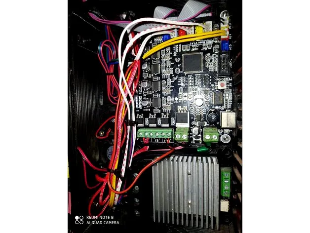
The original design of the Tevo Tarantula often routes the high current needed for the heated bed and hotend directly through the mainboard. This can place a significant strain on the mainboard’s components, particularly the traces and connectors responsible for delivering power. Over time, this constant stress can lead to overheating, premature wear, and even potential failure of the mainboard. The mainboard’s onboard relays are often not designed to handle the continuous high current draw of these components, leading to a shorter lifespan or potentially causing the printer to malfunction. Furthermore, voltage drops across the mainboard can reduce the effective power delivered to the heated bed and hotend, resulting in slower heating times and inconsistent temperatures, which directly impact print quality. These power issues often manifest as thermal runaway errors or the printer simply failing to heat up properly.
The Role of a MOSFET
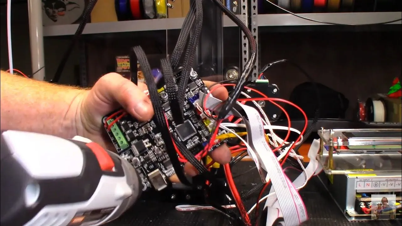
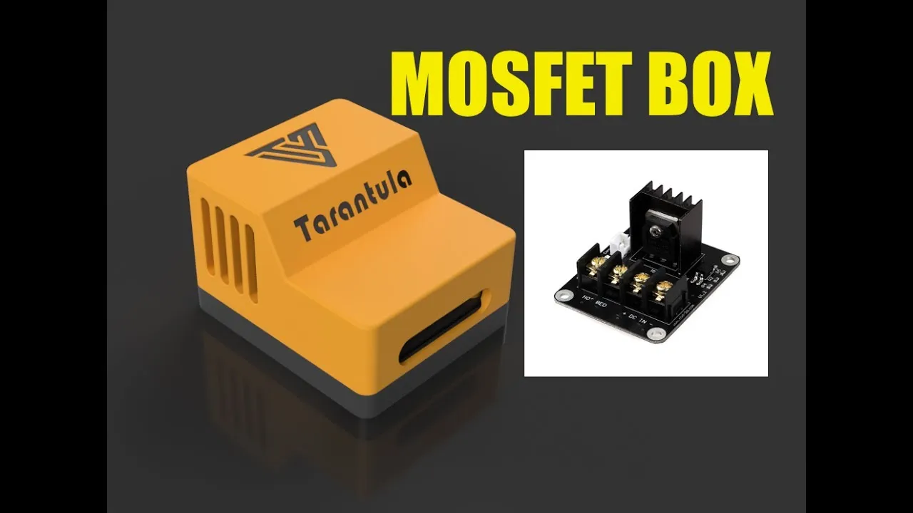
A MOSFET acts as an electronic switch, essentially taking the heavy lifting of power delivery away from the mainboard. It is inserted in the circuit between the power supply and the heated bed and/or hotend. The mainboard still controls the heating elements by sending a low-voltage signal to the MOSFET, but the MOSFET itself then switches the high-current power from the power supply to the components. This means that the mainboard only needs to handle a small control current, greatly reducing the risk of overheating and damage. The MOSFET efficiently handles the high current required, ensuring that the heated bed and hotend receive the full power they need for optimal performance. This setup significantly improves the reliability and safety of your 3D printer, while also allowing for faster heating times and more consistent temperatures, leading to better print results.
Benefits of a MOSFET Upgrade
Upgrading your Tevo Tarantula with a MOSFET offers a multitude of benefits. The most important advantage is improved safety, as it significantly reduces the risk of fire and damage to your printer. By offloading the high-current load from the mainboard, you protect its sensitive components from overheating and failure. In addition to safety, a MOSFET upgrade provides enhanced performance. You can expect faster heating times for both the heated bed and hotend, allowing you to start printing sooner. The more stable temperature control resulting from the upgrade contributes to better print quality, with fewer issues related to warping or poor layer adhesion. Finally, a MOSFET upgrade extends the lifespan of your 3D printer by reducing the stress on the mainboard. This is a relatively inexpensive upgrade that offers significant improvements in safety, performance, and longevity for your Tevo Tarantula.
What You’ll Need for the MOSFET Upgrade
Required Components and Tools
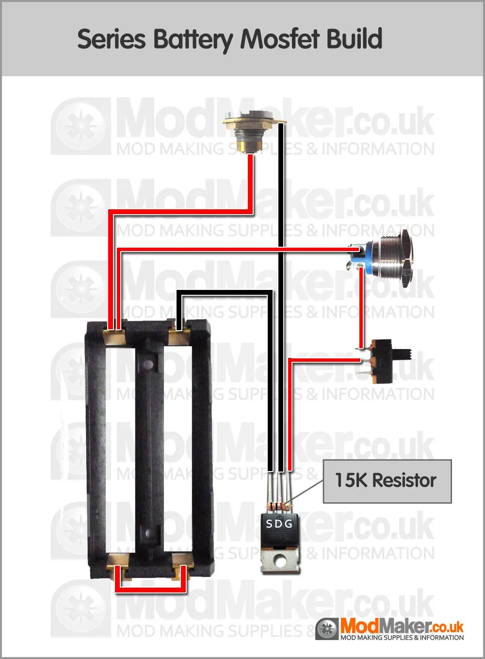
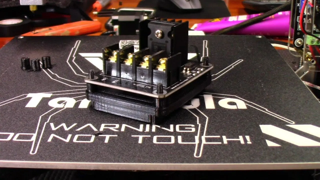
Fortunately, the components needed for a MOSFET upgrade are relatively inexpensive and easy to obtain. You’ll need a MOSFET module designed for 3D printers. These modules typically come with all necessary connectors and wires, making the installation process simpler. Make sure to select a MOSFET module that is rated for the current draw of your heated bed and hotend, usually around 10-15 Amps. Also, you’ll need a soldering iron, solder, and optionally, heat shrink tubing to insulate the connections. Other essential tools include a wire stripper, a screwdriver, and a multimeter. A multimeter is helpful for verifying the wiring and ensuring proper connections. Finally, you might need a mounting bracket to secure the MOSFET module to the printer frame. Having these tools and components readily available will make the upgrade process much smoother and more efficient. Always unplug the printer from the power source before beginning any electrical work.
Step-by-Step MOSFET Installation Guide
Preparing the Tevo Tarantula for Upgrade
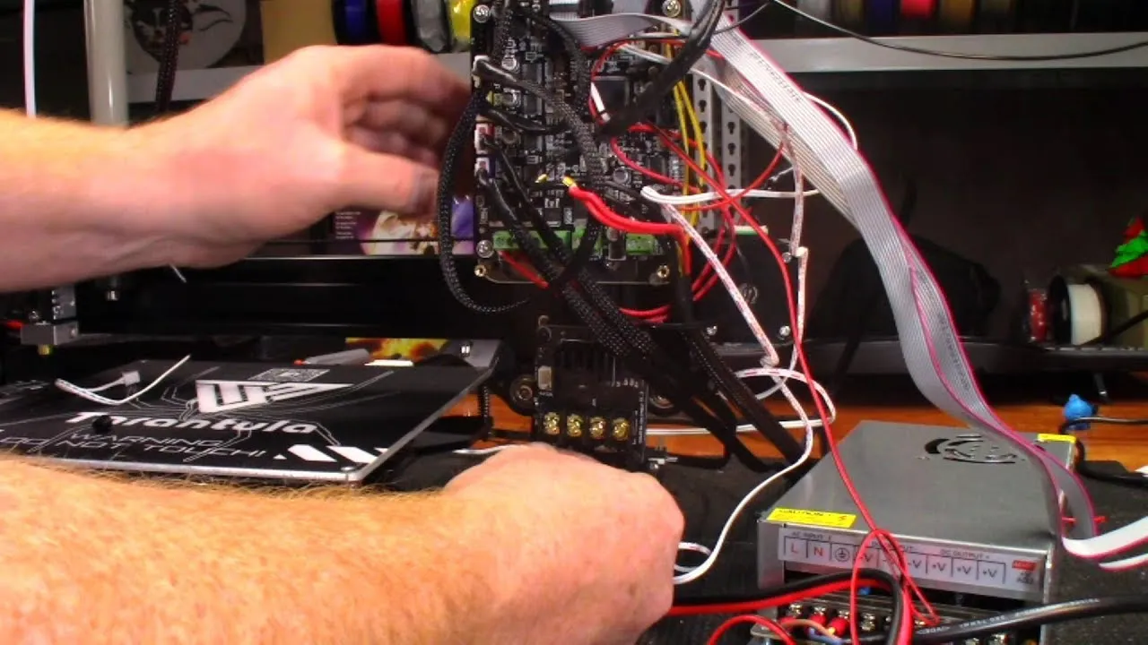
Before starting the installation, ensure the Tevo Tarantula is unplugged from the power outlet. Disconnect the power supply wires from the mainboard that connect to the heated bed and hotend. Identify the positive and negative terminals on both the mainboard and the heated bed/hotend. It’s a good practice to take pictures before you start to document the original wiring configuration for easy reference. This will help you to ensure that you reconnect everything correctly. Once the power supply wires and the heated bed/hotend wires have been disconnected from the mainboard, you’re ready to start connecting the MOSFET module.
Connecting the MOSFET to the Power Supply
The MOSFET module typically has two sets of terminals for the power supply. Connect the power supply wires that were previously connected to the mainboard to the input terminals of the MOSFET. This is where the high-voltage power from the power supply enters the MOSFET. Next, connect the output terminals of the MOSFET to the heated bed and hotend. Ensure that you connect the wires with the correct polarity, matching positive to positive and negative to negative. If your MOSFET module has a separate control input, connect this to the appropriate terminals on the mainboard that originally controlled the heated bed and/or hotend. Double-check all connections to ensure they are secure and properly insulated, using heat shrink tubing if necessary. Refer to the MOSFET module’s documentation and any diagrams you took earlier to confirm the correct connections.
Wiring the Heated Bed and Hotend
After connecting the power supply and the control signal, it’s time to wire the heated bed and hotend to the output terminals of the MOSFET. These terminals provide the power to the heated bed and hotend, as controlled by the MOSFET. Connect the wires from the heated bed and hotend to the output terminals, making sure to observe the correct polarity. The heated bed will typically have two wires, and the hotend will also have two wires. Securely tighten all the screws on the terminals to prevent any loose connections, which can lead to arcing or other issues. Once all the wiring is complete, carefully inspect all connections to ensure they are correctly wired and properly insulated. You can use heat shrink tubing to insulate any exposed connections, and also to neaten the wiring. Double-check all connections against the MOSFET module’s diagram and your original wiring pictures to make sure everything is in order.
Testing and Calibration
With the MOSFET installed, it’s time to test and calibrate your printer. Before plugging in the printer, visually inspect all connections one last time to ensure that everything is secure. Then, plug in the power supply and turn on the printer. Use the printer’s control panel or slicing software to preheat the heated bed and hotend. Monitor the temperature readings to ensure they are reaching the desired temperature and that the heating is consistent. If you see any errors or the heated bed and hotend are not heating up, immediately turn off the printer and check all connections. A multimeter can be used to verify the voltage across the heated bed and hotend terminals. If the temperatures are behaving as expected, you can now start the calibration process. This involves adjusting the PID settings for the heated bed and hotend, which will fine-tune the temperature control. Refer to your printer’s manual or online guides for instructions on PID calibration.
Troubleshooting Common Problems
Bed Not Heating Up
If the heated bed isn’t heating up, first check the power supply. Make sure the power supply is turned on and delivering the correct voltage. Then, inspect the connections on the MOSFET module, ensuring all wires are properly connected and making good contact. Use a multimeter to test for voltage at the output terminals of the MOSFET module when the heated bed should be on. If there is no voltage, the MOSFET module may be faulty, or the control signal from the mainboard isn’t reaching it. Check the wiring between the mainboard and the MOSFET module to make sure the control signal is being sent. If the wiring looks good and the MOSFET module still isn’t working, the module itself may need to be replaced. Also, make sure the thermistor for the heated bed is correctly connected and functioning properly. A faulty thermistor can prevent the heated bed from heating up.
Hotend Not Heating Up
If the hotend isn’t heating up, the troubleshooting steps are similar to those for the heated bed. Check the power supply voltage and ensure it’s functioning correctly. Inspect the connections on the MOSFET module for the hotend, ensuring all wires are properly connected. Use a multimeter to test for voltage at the output terminals of the MOSFET module when the hotend should be heating. If there is no voltage, the MOSFET module may be faulty or the control signal from the mainboard isn’t reaching it. Check the wiring between the mainboard and the MOSFET module to ensure the control signal is being sent. Also, check the hotend’s thermistor. Ensure that it is correctly connected and functioning, as a faulty thermistor can prevent the hotend from heating up. Inspect the hotend itself for any blockages or other issues that might prevent it from reaching the desired temperature.
MOSFET Overheating
If the MOSFET module is overheating, it’s an indication that it is working too hard, which can lead to premature failure. Ensure that the MOSFET module is rated for the correct current draw for your heated bed and hotend. A module that is undersized can easily overheat. Check the wiring connections for any loose or poorly made connections, as these can create resistance and generate heat. Verify that the heated bed and hotend are functioning properly and aren’t drawing excessive current. Make sure the MOSFET module has adequate ventilation. If the module is enclosed, consider providing additional cooling, such as a small fan, to help dissipate the heat. If the MOSFET module continues to overheat, consider replacing it with a higher-rated model. In some cases, the mainboard might still be delivering a small amount of current to the heated bed or hotend, even when the MOSFET is supposed to be controlling the power. Check your mainboard settings and firmware to make sure this isn’t happening.
Maintenance and Safety
Regular Checks and Maintenance
Regular maintenance is crucial to ensure the longevity and safety of your 3D printer after the MOSFET upgrade. Periodically inspect all wiring connections to ensure they are secure and free from any signs of wear or damage. Look for any loose connections, frayed wires, or signs of overheating. Clean any dust or debris that may accumulate on the MOSFET module, as this can impede its ability to dissipate heat. Regularly check the heated bed and hotend for any signs of wear or damage, such as warping or cracking. Make sure to routinely calibrate the printer’s temperature settings to ensure optimal performance. By performing these regular checks and maintenance tasks, you can identify and address potential issues before they become major problems, extending the life of your 3D printer and ensuring safe operation.
Safety Precautions During Operation
Safety should always be your top priority when operating your 3D printer, especially after making any modifications. Never leave your 3D printer unattended while it is in operation, especially during longer prints. Keep flammable materials away from the printer, as the heated bed and hotend can reach high temperatures. Always unplug the printer from the power outlet before performing any maintenance or repairs. If you notice any unusual odors, sounds, or smoke, immediately turn off the printer and unplug it. It’s important to follow all safety guidelines provided by the manufacturer of your 3D printer and any third-party components you install. If you are unsure about any aspect of the installation or operation of your printer, consult a qualified technician. By practicing these safety precautions, you can minimize the risks associated with 3D printing and enjoy a safer and more enjoyable experience.
